Experiencing in pieces kit index
Experiencing in Pieces: A Physical Computing Approach to Sonic Composition
Steven Smith
North Carolina State University
Jeremiah Roberts
North Carolina State University
 Instruction Set: Prototyping Experiencing in Pieces
The instruction set provided herein is not for an exact replication of Jeremiah Roberts’ “Experiencing in Pieces;” rather, it is designed to create a much smaller-scale project for a more beginner audience. Jeremiah’s project used eight projectors and two Kinects, and this version is being designed for one projector and one Kinect. Using these basic components, users will be able to add more Kinects and projectors if desired. The following elements will be necessary:
Software and Interface Requirements
- TouchDesigner — to control the project’s interface, track human motion, and enable distribution of audio and video
- Audio Recording Software—to record or edit music tracks, as well as render them out separately
- Optional: Video Editing Software—to record and edit videos (if desired)
Hardware Requirements:
- PC with multiple output ports for projections (USB 3.0 required)
- Microsoft Kinect V2 for PC
- Optional: Tripod (for Microsoft Kinect, unless mounted elsewhere)
This instruction set assumes that users will have their own audio files to work with, and will not cover the basics of editing audio or video rendering. That said, tutorials can be easily access online, and we prefer either Audacity or Adobe Audition. This instruction set also assumes that users will have a working knowledge of the Microsoft Kinect SDK—the software used to use a Kinect on the PC. Again, tutorials can be easily accessed online, and in most cases it is as simple as downloading the SDK.
Before beginning this project, it should be noted that some knowledge of TouchDesigner may be necessary, though we do believe that the most novice of creative coders can follow the instructions provided. TouchDesigner also has a colorful community that can be found on Facebook and the www.derivative.ca website that is open to questions and providing aid when needed. Several videos on YouTube and Wikipedia may also allow one to understand the concepts behind the software, and one may even consider the book An Introduction to TouchDesigner by Elburz Sorkhabi, an invaluable work that aided in the production of this project.
Section One: Connecting the Kinect to TouchDesigner
In this first section, users will gain a basic understanding of TouchDesigner’s dialogs, how to place nodes, how to connect nodes, and how to modify the parameters of each node. This introduction will serve as the basis for the following sections.
Step 1: TouchDesigner and the Kinect
Begin by opening the TouchDesigner software. Once opened, users should see a blank “grid” which should take up the majority of their screen. Right click to bring up a list of software options and click “Add Operator.” Users will then see a “Create dialog” menu with six tabs at the top (COMP, TOP, CHOP, SOP, MAT, and DAT). Click TOP for now, and then select Kinect. Place the “node” anywhere on grid.
Note: You may also press “tab” instead of right clicking to get to the dialog menu.
Step 2: Adding Nodes
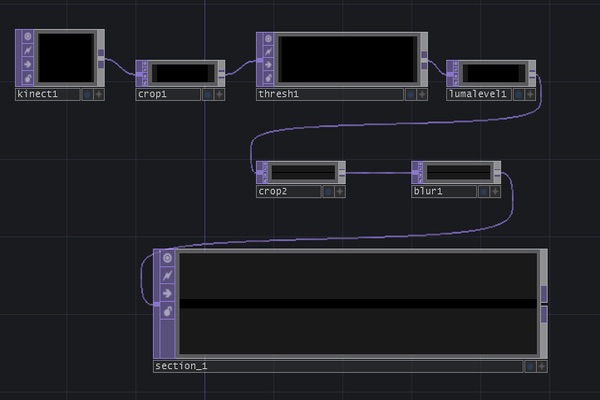
Repeating the same process, click tab to enable the dialog menu. With TOP selected again, select a CROP TOP. Repeat this process for the following: THRESHOLD TOP, LUMA LEVEL TOP, a second CROP TOP, a BLUR TOP, and a third CROP TOP. Scaffold each node as you wish, but be sure to place them in the same order as they are previously listed.
Step 3: Connecting Nodes
Note: This chain is used to crop and alter the body so it can pick up a white blur of the human body at the mid-section to account for people of all sizes, no matter how tall or short.
Once there are a total of seven nodes, the user should use their mouse and connect each TOP via wiring operators. This is done by left clicking either the input or output section on each node and dragging a wire to another node’s input/output. There should be a total of six wiring operators connecting each node. Once this has been achieved, rename the third CROP TOP “section 1” by clicking on the text “crop3” within the node. At this point, your project should look something like Figure 1 (below). There may or may not be a white blur in each section, depending on the location of your Microsoft Kinect.
Step 4: Setting Parameters
For each TOP, specific parameters may need to be set in accordance with the location of the project. Below, we have provided the parameters that were used in Jeremiah’s project, but these may need to be slightly altered depending on the size of the room or the light emitted within the room. Essentially, you will want to alter the THRESHOLD and LUMA levels to allow the Kinect to register you as a white blur, making you easily trackable.
Begin by clicking on CROP 1. If necessary, press “P” to open the parameters command prompt. As you can see, there several options for modifying the content of each node. For purposes of learning, change the parameters to the following specifications:
- Crop left: 0
- Crop right: 1
- Crop bottom: 0
- Crop top: 0.373
- Extend: Repeat
Repeat this process for the following nodes: THRESHOLD, LUMA LEVELS, CROP1, and BLUR1:
THRESHOLD |
LUMA LEVELS |
CROP2 |
BLUR1 |
|---|---|---|---|
Comparator: Not Equal |
Source: Luminance |
Crop Left: 0 |
Method: Horizontal and Vertical |
RGB: Luminance |
Invert: 0.843 |
Crop Right: 1 |
Type: Catmull-Room |
Threshold: .355 |
Black level: 0 |
Crop Bottom: 0.416 |
Extend: Hold |
Alpha: Same as RGB |
Brightness: 2 |
Crop Top: 0.49 |
Pre-Shrink: 3 |
Soft: 0.213 |
Gamma 1: 1.9 |
Extend: Repeat |
Filter Size: 30 |
Contrast: 1.09 |
Sample Step: 1. 1. P. |
Section 1 Conclusion
By the time you wrap this section up, the TouchDesigner interface should look similar to Figure 1, albeit the parameters of each node should be modified. Depending on the specifications of your room, these parameters may need to be altered—room size and lighting may play a role in how the Kinect receives bodily input. One strategy we employed that we found worked best was changing the Image in the KINECT TOP node to Player Index. This gave us maximum range on the Kinect for sensing the body. We also tried infrared, but ultimately decided against it because the range was rather limited. If you are operating in a smaller room, using infrared or raw depth might suit you well. Once these steps have been completed and you have met your desired specifications, continue to Section 2: Adding Media files.
Section 2: Adding Media Files
In this section, users will learn how to add audio files to the TouchDesigner software. This section is relatively simple with basic knowledge of uploading principles.
Step 1: Add an AUDIO FILE DEVICE IN from CHOP
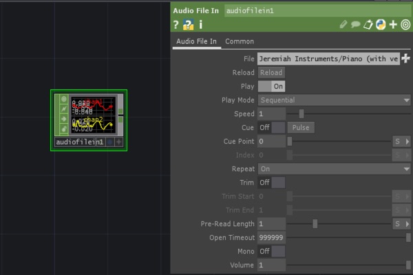
Right click anywhere on the grid and click “Add Operator” (or simply press tab). Click on the tab CHOP and then select AUDIO FILE IN. Place this node in any desired location. In the parameters section, click on the + sign and add the desired audio file or effect.
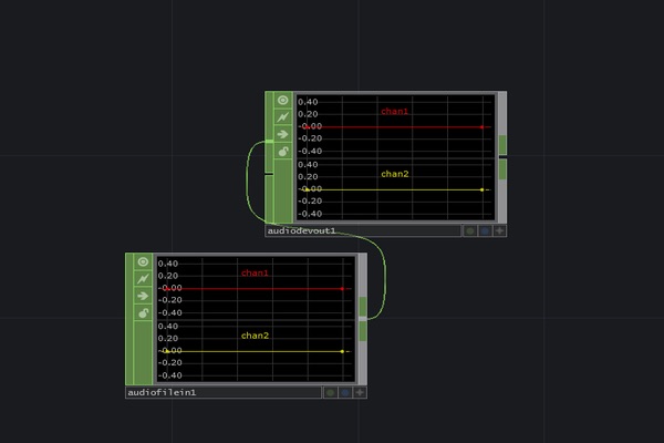
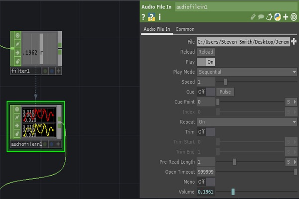
Step 2: Add an AUDIO FILE DEVICE OUT from CHOP
Right click near the previously added CHOP and press tab on your keyboard. Under the tab CHOP, click AUDIO DEVICE OUT CHOP and place it in somewhat close proximity to the previously added node. Wire the two nodes together, as seen in Figure 3.
Step 3: Add a MOVIE FILE IN from TOP
Press tab on the keyboard and select the tab TOP. Select MOVIE FILE IN and place it with the previously created nodes. Select a file via the + button on the parameters panel.
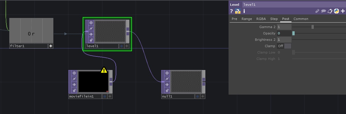
Step 4: Adding LEVEL and NULL TOPS
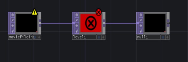
Note: The TOPs connected in Step 4 will ultimately allow the body to act as the “switch” for playing music and turning on the video.
Press tab on the keyboard and add a LEVEL TOP. Repeat this process and add a NULL TOP. Wire the two nodes to the SWITCH TOP as seen in the figure below. Ignore the Red X on the node for now.
Section 2 Conclusion
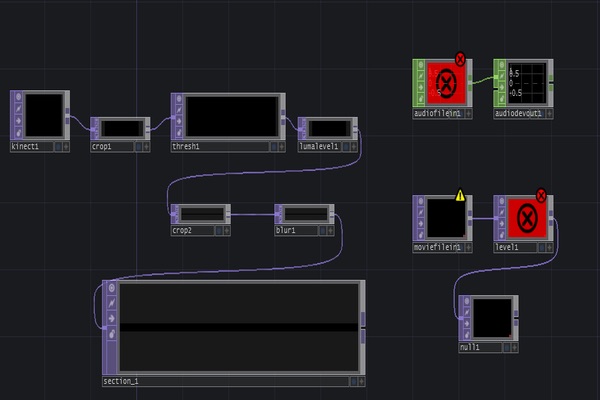
Before proceeding, make sure that the parameters of LEVEL TOP have been modified and that you have successfully uploaded your desired media files. Your project should now look similar to Figure 5 (below).
Section 3: Motion Analysis and Data Comprehension
This section will descibe analyzing motion and sending movement to the SWITCH TOP made in Section 2. That being said, this is the most technical part of this assignment and one that may need to be worked out through a trial and error process. The steps provided in this section should guide you towards a working installation, but if an error occurs, remember that the TouchDesigner community is there to help if you are unable to solve the problem yourself.
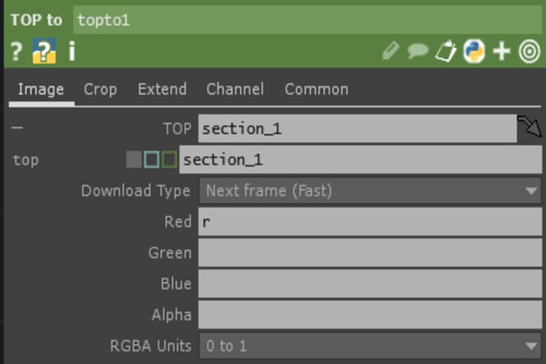
Step 1: Add a TOP to CHOP
Press tab and create a TOP to CHOP. In the TOP to parameters section, delete all letters written in the color columns except for “r.”
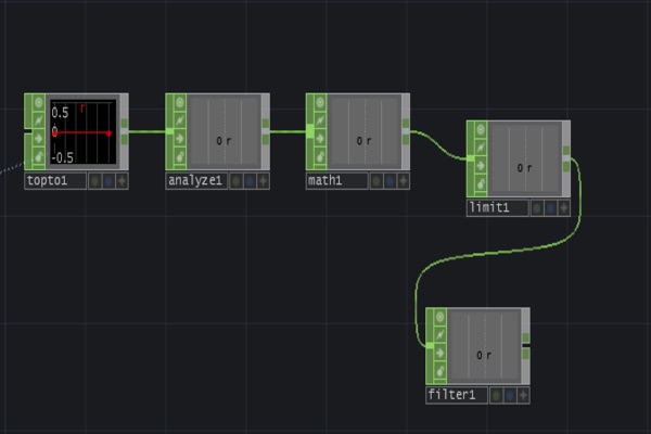
Step 2: Add an ANALYZE CHOP, MATH CHOP, and a LIMIT CHOP
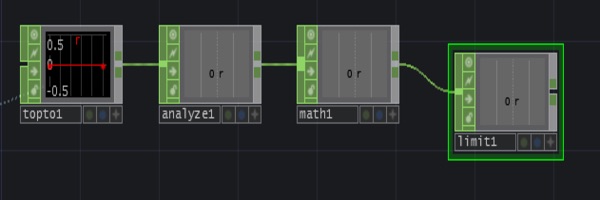
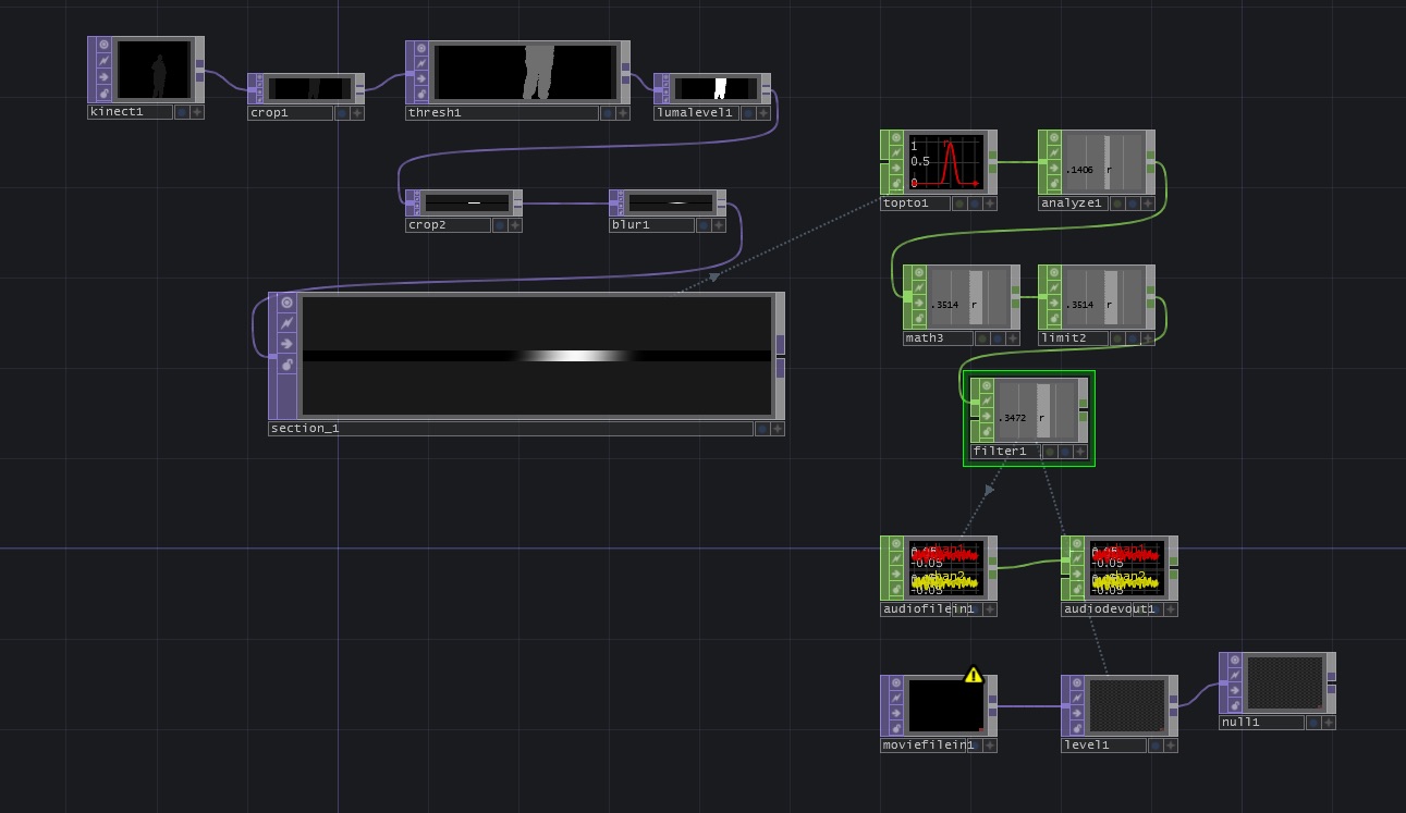
Press tab and add an ANALYZE CHOP, a MATH CHOP, and a LIMIT CHOP. Wire each node together, beginning with the TOP to CHOP. Your nodes should now be connected and look like Figure 7.
Step 4: Add a FILTER CHOP
Press tab and add a FILTER CHOP. Wire the LIMIT CHOP to the FILTER CHOP. The cluster of nodes created during steps 1-4 should now resemble figure 8.
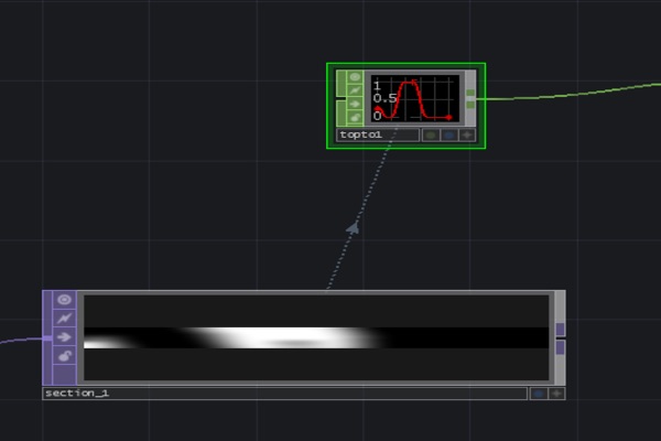
Step 5: Connecting section_1 (previously CROP2 TOP) to TOP to CHOP
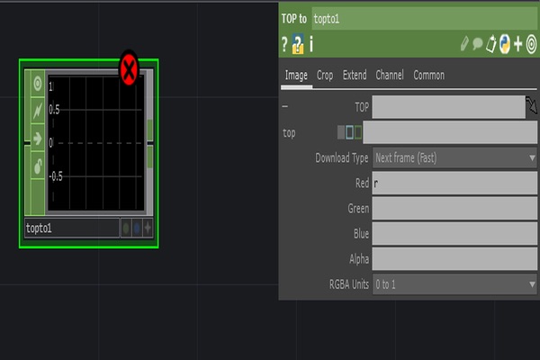
Select the node TOP to CHOP—you should see the parameters box open for said node; if you do not, press P. Now, using your mouse or mousepad, click and hold section_1. If this is done correctly, a white arrow should appear when you move your mouse or mousepad. Drag the white arrow to the parameters box of TOP to CHOP and place it in the TOP rectangle. If done correctly, your TOP to CHOP parameters should look like Figure 9.
By doing this, you should have created a link between the section_1 TOP and the TOP to CHOP. An arrow should show the two connected, as seen in figure 10. There should no longer be a red X on the box, but in its place a red line that may or may not be moving given the location of your Kinect.
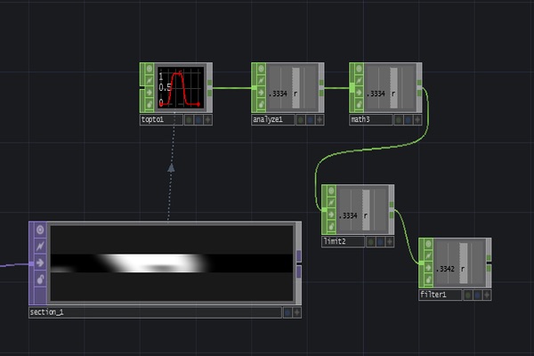
Additionally, there should now be a set of numbers on the CHOPs connected to TOP to CHOP, as seen in figure 11.
Step 6: FILTER CHOP to AUDIO FILE IN CHOP
This process is similar to step 5, wherein we connected the section_1 TOP to the TOP to CHOP. To begin, select the AUDIO FILE IN CHOP and make sure the parameters box is open. Left click on your mouse or mousepad and drag the FILTER CHOP to the volume section of the AUDIO FILE IN CHOP. If this does not work for you the first time, you may need to click the + on the bottom right hand corner of the FILTER CHOP node to lock it. You should now see a connection between the AUDIO FILE IN CHOP and the FILTER CHOP, and the parameters volume should match the numbers on the FILTER CHOP node.
Step 7: FILTER CHOP to LEVEL TOP
Similar to step 6, select the node LEVEL TOP and make sure the parameters box is open. Left click on your mouse or mousepad and drag the FILTER CHOP to the opacity parameter of the LEVEL TOP. The numbers in index should mimic the numbers of the FILTER CHOP. As you can see, mine says 0 because my Kinect is not registering me. If your Kinect is near you, these numbers may be different.
Step 8: Adding an Outsource
Press tab and select the COMP tab, and then choose a WINDOW COMP. Place it near the NULL TOP. Next, drag the NULL TOP into the WINDOW COMP and select Parm: Operator. Once this has been completed, click the WINDOW COMP to bring up the parameters and select Open as Perform Window: Perform (near the bottom). This should open up the performance window of TouchDesigner. Standing in front of your Microsoft Kinect should now activate the music and the video in the full screen performance window.
Section 3 Conclusion
At this point, the project should be in working order, barring the necessities of messing with the parameters depending on the location of the project and choosing the correct output device for your project in the WINDOW COMP node. The entirety of your project should be 18 nodes. The project in its entirety should look something like Figure 14.
Troubleshooting
The Microsoft Kinect can be an extremely finicky device when working with the PC, therefore it may create some problems for some users. Typically, opening the Kinect SDK on your computer and running the Configuration Verifier will fix the majority of these problems. In rare cases, you may have to delete the Kinect node and create a new one, keeping in mind the Image parameter. Again, this was a rare occurrence for us and one you will likely not encounter.
Conclusion
As stated at the beginning of this document, this instruction set is somewhat difficult and some working knowledge of TouchDesigner may be required, though some users will undoubtedly find this an excellent alternative to written-based coding languages such as Java. You may simply repeat this process to add more interactive nodes, but keep in mind there are limitations based on how large your room is, or how many projectors you have access to—the free version of TouchDesigner also does not allow one to display an image past 1280x1280 resolution. In order to remain true to Jeremiah’s version, I wanted to include how to incorporate a video component to the project, but many of us interested in sound studies and sonic composition may opt out of using the video component. In such cases, you may simply run your FILTER CHOP to a NULL TOP and then the NULL TOP to a WINDOW COMP.
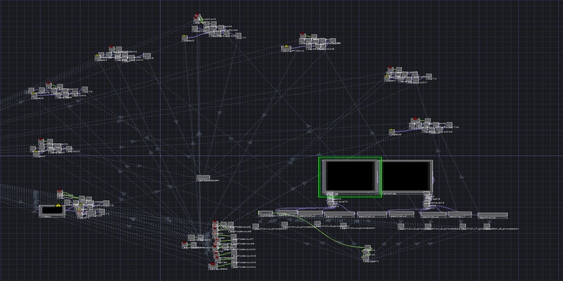
This project could be used as a class-based project wherein student groups collaborate to create interesting soundscapes that are interacted with via the Microsoft Kinect. TouchDesigner could undoubtedly be a valuable contribution to sonic composition with or without the Kinect, and those of us interested in the relationship between the sound and the body will find this project fruitful for generating other ideas using the software. The software itself is extremely powerful, and we are only scratching the surface via the 18 nodes created in this project. Jeremiah’s project (see image below) was much larger in scale, and we hope that future projects will be even larger.